
Ever wondered how your CAT C15 engine manages to roar to life and perform with such incredible power? At the heart of this intricate machinery lies a sophisticated electronic control module (ECM), known affectionately as the “brain” of the engine. This digital powerhouse receives a deluge of information, processes it with lightning speed, and sends commands to various components, ensuring smooth and efficient operation. The key to understanding this intelligence lies within the 70-pin connector that links the ECM to the rest of the engine; a complex web of wires carrying critical data signals.

Image: wiringschematiclaura55.z21.web.core.windows.net
This article delves into the fascinating world of the CAT C15 70-pin ECM wiring diagram. We’ll unravel the intricacies of this intricate system, exploring the pin assignments, the information they carry, and their impact on your engine’s performance. Whether you’re a seasoned mechanic or just curious about the technology that powers your powerful truck, this journey will provide valuable insights into the heart of your CAT C15 engine.
A Glimpse into the ECM’s Domain: Understanding the 70-Pin Connector
The CAT C15 70-pin ECM connector serves as the central communication hub for your engine. Each pin within this connector is assigned a specific function, responsible for transmitting or receiving critical information from various sensors and actuators. These signals, ranging from engine speed and temperature to fuel pressure and injection timing, play a crucial role in fine-tuning the engine’s performance and ensuring optimal efficiency.
Deciphering the Code: Pin Assignments and Their Significance
The 70-pin connector is a complex network, and understanding its pin assignments is essential for diagnosing engine problems, troubleshooting electrical issues, and even upgrading performance. Let’s break down the key pin groups and associated functions:
1. Power and Ground: The Engine’s Lifeline
- Pins 1-5: These pins are responsible for providing power to the ECM and grounding the system. A steady flow of electricity is essential for the ECM to operate correctly and send the necessary control signals to the engine components.
- Pins 6-10: These pins handle additional ground connections, ensuring a stable and reliable electrical environment for all ECM operations.
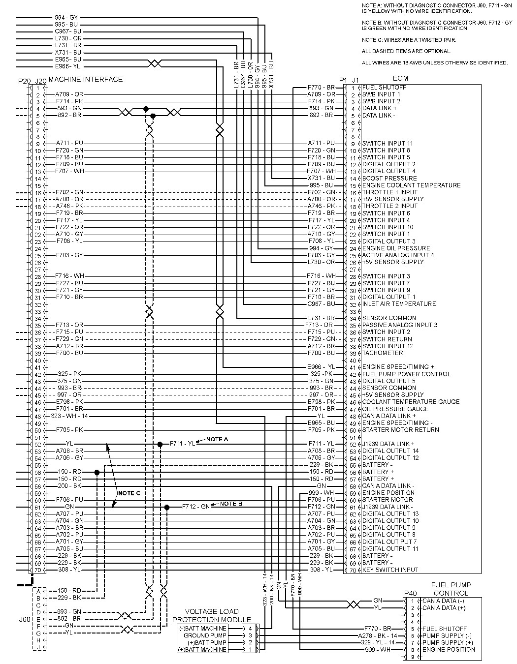
Image: enginelibraul.z6.web.core.windows.net
2. Sensors: The Engine’s Eyes and Ears
- Pins 11-20: This group houses connections for various sensors that monitor critical engine parameters. These include:
- Engine Speed Sensor: Tracks the engine’s RPM, vital for accurate fuel injection and ignition timing.
- Crankshaft Position Sensor: Detects the crankshaft position, crucial for determining the precise timing of each combustion cycle.
- Coolant Temperature Sensor: Measures the engine coolant temperature, allowing the ECM to adjust fuel mixture and coolant flow for optimal operating temperatures.
- Intake Air Temperature Sensor: Provides the ECM with information about the air temperature entering the intake manifold, crucial for calculating the correct fuel-air ratio.
- Barometric Pressure Sensor: Measures atmospheric pressure, enabling the ECM to adjust fuel delivery based on altitude and air density.
- Pins 21-30: This group accommodates additional sensor connections for:
- Fuel Pressure Sensor: Monitors fuel pressure within the common rail system, ensuring optimal fuel delivery to the injectors.
- Fuel Level Sensor: Tracks the fuel level in the tank, providing a warning when fuel is low.
- Oil Pressure Sensor: Measures oil pressure within the engine, alerting the ECM to any potential problems in the lubrication system.
- Transmission Temperature Sensor: Monitors transmission fluid temperature, allowing the ECM to ensure optimal transmission functionality.
3. Actuators: The Engine’s Muscles
- Pins 31-40: This group connects to various actuators that respond to ECM commands, controlling engine functions:
- Fuel Injectors: The ECM controls the timing and duration of fuel injection, optimizing combustion and power output.
- Engine Stop Solenoid: This solenoid cuts off fuel supply, stopping the engine upon command.
- Turbocharger Boost Control Solenoid: Regulates turbocharger boost pressure, ensuring optimal air intake and engine performance.
- EGR Valve Solenoid: Controls the flow of exhaust gases back into the combustion chamber, reducing emissions and optimizing fuel efficiency.
- Pins 41-50: Additional actuators connected to these pins include:
- Transmission Control Solenoid: Manages gear shifting and transmission operation, providing smooth and efficient power delivery.
- Electric Fan Control Module: Regulates fan speed, ensuring optimal cooling for the engine.
- Alternator Control Module: Regulates alternator output, ensuring a stable electrical supply to the vehicle’s systems.
4. Communication and Data: The Engine’s Brain
- Pins 51-60: This group is responsible for data communication between the ECM and other vehicle components.
- Data Bus: This network allows the ECM to share information with other modules, such as the instrument cluster, transmission control unit, and other vehicle systems.
- Pins 61-70: These pins handle additional data communication functions, as well as diagnostic and programming connections.
Navigating the Diagram: Tools and Techniques
Understanding the CAT C15 70-pin ECM wiring diagram is a crucial skill for anyone working on this powerful engine. Here are some tools and techniques that will help you decipher this complex network:
1. The Diagram’s Anatomy:
- Pin Numbers: Every pin is numbered for easy identification.
- Wire Colors: Each wire is typically color-coded for easy tracing.
- Circuit Descriptions: Each pin is assigned a clear description of the circuit it carries.
2. Tracing Signals:
- Multimeter: A multimeter is essential for measuring voltage, resistance, and continuity, allowing you to trace signals through the wiring harness.
- Wire Tracing: Follow the color-coded wires from the ECM connector to their destination components.
- Troubleshooting Charts: Use diagnostic charts or manuals to pinpoint specific circuits and components based on symptoms.
Cat C15 70 Pin Ecm Wiring Diagram
https://youtube.com/watch?v=p8HxzEwLfAo
Conclusion: Your Path to Engine Mastery
The CAT C15 70-pin ECM wiring diagram is a complex but essential resource for anyone seeking to understand the intricate workings of your engine. By delving into the pin assignments and understanding the information they carry, you gain valuable insights into how the ECM controls and manages crucial engine functions. Whether you are troubleshooting a performance issue, performing a repair, or simply seeking to understand the technology that powers your powerful engine, a deep understanding of this diagram is crucial. Armed with this knowledge, you’ll have a more comprehensive grasp of how the ECM ensures the smooth and powerful operation of your CAT C15 engine.


