
Imagine a world without precise measurements – where bridges sway precariously, machines malfunction, and even the simplest gadgets fail to function. Engineering, the backbone of our modern world, relies heavily on accurate and consistent dimensional tolerances. Enter the world of GD&T symbols – a language of geometric dimensioning and tolerancing that empowers engineers to communicate precise design requirements with absolute clarity.

Image: mungfali.com
GD&T symbols are not merely cryptic markings on engineering drawings; they are the silent architects of precision, ensuring that manufactured parts fit seamlessly and perform flawlessly. Whether you’re an aspiring engineer, a seasoned professional, or simply curious about the intricate workings of the world around you, understanding the power of GD&T symbols will unlock a whole new perspective on engineering excellence.
A Journey into the World of Precision
The concept of GD&T, an acronym for Geometric Dimensioning and Tolerancing, emerged in the early 20th century as a response to the growing complexity of industrial products. Before GD&T, engineers relied on simple linear dimensions – length, width, and height – to define the shape and size of parts. However, this approach proved inadequate as designs became more sophisticated and tolerances tighter.
GD&T revolutionized engineering by introducing a structured system of symbols and rules to define a part’s size, form, orientation, and location with unparalleled precision. These symbols are not merely descriptive; they convey precise engineering intent, leaving no room for ambiguity.
Unveiling the Fundamental Symbols: A Primer
The world of GD&T symbols might seem daunting at first glance, but it boils down to a handful of fundamental elements:
1. Datum Features: The foundation of GD&T revolves around datum features, which serve as reference points for establishing a precise coordinate system. Think of them as the fixed points on a blueprint, enabling accurate positioning of other components. Datum features are represented by letters (A, B, C, etc.) on engineering drawings.
2. Tolerance Zones: These zones define allowable deviations from the ideal geometry of a part. For example, a tolerance zone for a diameter might define the range within which a circular feature can vary without compromising functionality. Tolerance zones are typically represented by a circle or square enclosing a numerical value indicating the permissible deviation.
3. Feature Control Frames: These frames encapsulate the essence of GD&T, providing detailed specifications for each geometric characteristic. They contain a wealth of information, including:
* **Geometric Characteristic Symbol:** This symbol indicates the geometric property being controlled, such as straightness, circularity, flatness, parallelism, etc.
* **Datum Reference:** Identifies the datum features used for reference.
* **Tolerance Value:** Specifies the allowable deviation from the ideal.
* **Modification Symbols:**  Additional symbols that further refine the tolerance requirements.
4. Modifiers: GD&T offers a set of modifier symbols that provide nuanced instructions for controlling geometric characteristics. These modifiers can enhance the precision of the design by specifying specific conditions or limiting permissible deviations.
Beyond the Basics: Decoding the Nuances
While mastering the fundamental GD&T symbols is a crucial first step, truly understanding this language requires delving deeper into the intricacies of each symbol’s application:
- Straightness: Ensures that a line feature remains perfectly straight within the defined tolerance zone.
- Flatness: Guarantees that a surface maintains flatness within a specified tolerance zone.
- Circularity: Specifies the allowable deviation from a perfect circle.
- Cylindricity: Ensures that a cylindrical feature remains within the defined tolerance zone.
- Parallelism: Specifies that two features maintain parallelism within the defined tolerance.
- Perpendicularity: Requires that two features remain perpendicular to each other within the specified tolerance.
- Position: Determines the precise location of a feature relative to one or more datum features.
- Symmetry: Controls the symmetrical relationship between two features.
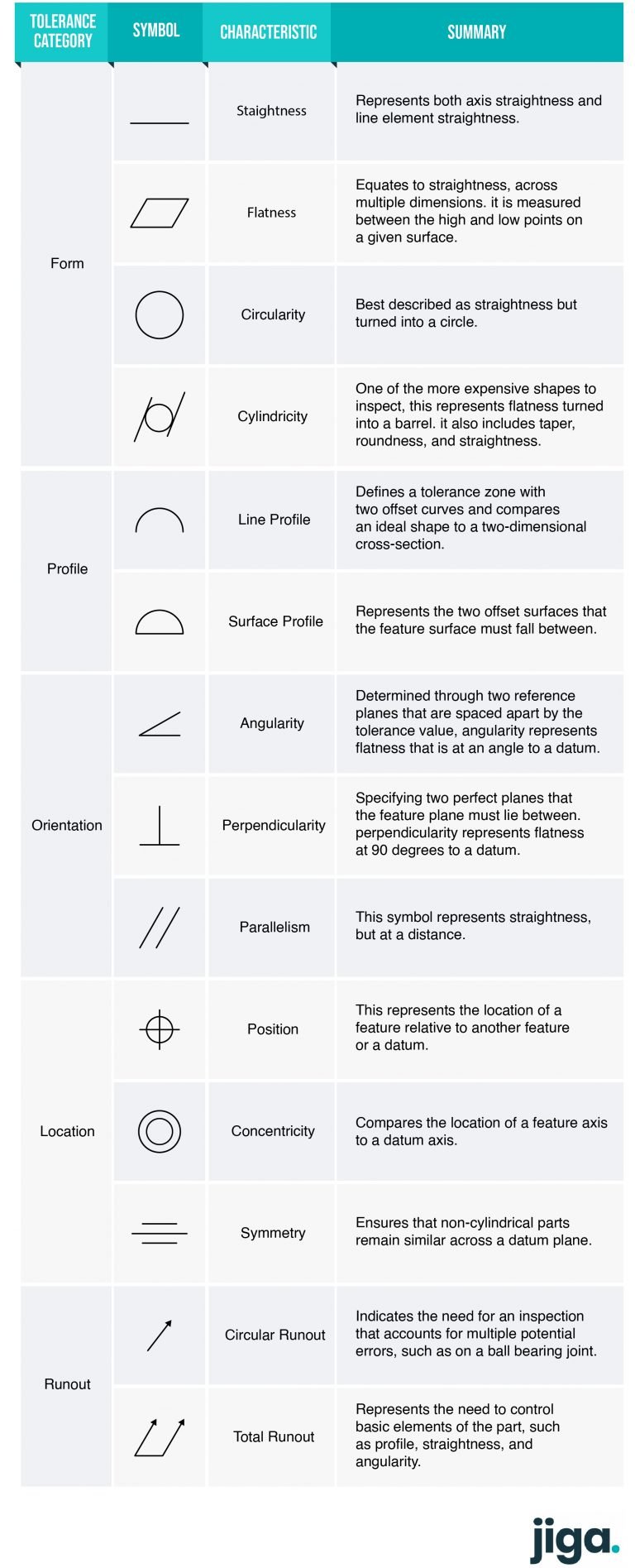
Image: animalia-life.club
The Benefits of GD&T: A World of Precision
The value of GD&T extends far beyond the realm of engineering drawings. Implementing GD&T principles translates into a multitude of tangible benefits:
- Enhanced Product Quality: By enforcing precise tolerances, GD&T ensures that manufactured parts function as intended, reducing defects and improving product reliability.
- Improved Communication: GD&T provides a standardized language for engineers and designers, ensuring clear communication of design intent.
- Reduced Costs: By eliminating the need for rework and minimizing scrap, GD&T contributes to overall cost savings.
- Simplified Inspection: GD&T symbols offer a streamlined approach to inspection, simplifying the process of verifying that parts meet design specifications.
Beyond the Manufacturing Floor:
The benefits of GD&T extend beyond the manufacturing floor and into various fields:
- Aerospace Engineering: Designing aircraft with stringent tolerance requirements for safety and performance.
- Automotive Industry: Ensuring the precision of components for optimal engine performance and vehicle stability.
- Medical Device Manufacturing: Creating implantable devices with extremely tight tolerances for patient safety and efficacy.
Navigating the Resources: Finding Your Way
Embarking on your journey to understanding GD&T might seem overwhelming, but numerous resources can guide you along the way:
- ASME Y14.5 Standard: The definitive guide to GD&T, covering symbols, definitions, and application guidelines.
- Online Tutorials: Numerous websites offer interactive tutorials and video lessons explaining GD&T concepts.
- Professional Training Courses: Several organizations offer in-depth training courses to develop your GD&T expertise.
- Industry Associations: Joining industry associations provides access to industry-specific GD&T resources and networking opportunities.
The Future of GD&T: Advancements and Innovations
GD&T is an evolving field, continuously adapting to meet the growing demands of precision engineering. Modern advancements include:
- 3D Modeling Integration: Integrating GD&T directly into 3D modeling software streamlines the design process.
- Automated GD&T Analysis: Sophisticated software tools automate the analysis of GD&T specifications, identifying potential conflicts and ensuring compliance with design intent.
- Virtual Reality (VR) for GD&T Training: VR simulations enhance the learning experience by providing immersive and interactive training environments.
G D And T Symbols Pdf
Embracing the Power of Precision
Understanding GD&T symbols is not merely a technical skill; it’s an investment in a future where precision reigns supreme. Whether you’re designing cutting-edge technology, building life-saving medical devices, or exploring the frontiers of engineering, mastering the language of GD&T will empower you to create a world where precision is the cornerstone of innovation.
Embrace the challenge, unlock the power of GD&T, and step into a world of precision where every detail counts.


