
Imagine a bustling factory floor, where machines hum and whir, propelling production forward. At the heart of this automated symphony lies the 3-phase motor – a powerful workhorse that drives countless industrial processes. But before these motors can unleash their power, they need a crucial intermediary: a motor starter. This seemingly simple device acts as the brain, controlling the flow of electricity and protecting the motor from damage. And at the core of understanding motor starter operation lies the intricate 3-phase motor starter wiring diagram.

Image: 2020cadillac.com
As someone who’s spent years immersed in the electrifying world of industrial automation, I can confidently say that deciphering these wiring diagrams initially seemed like an impossible puzzle. But with patience, practice, and the right resources, I came to appreciate the elegance and logic woven into every wire connection. Today, I want to share my insights, guiding you through the world of 3-phase motor starter wiring diagrams, demystifying the process and empowering you to confidently troubleshoot, wire, and maintain these essential components.
Navigating the Labyrinth of 3-Phase Motor Starter Wiring
Let’s embark on a journey to unravel the complexities of this crucial wiring diagram. At its essence, it depicts the interconnections between the motor starter components, revealing how electricity flows and controls the motor’s operation. Understanding these diagrams is fundamental for anyone involved in the installation, maintenance, or troubleshooting of industrial machinery.
Think of this wiring diagram as a blueprint, mapping the pathways of electrical currents that bring the motor to life. Each line on the diagram represents a wire, while symbols depict components such as the motor itself, the starter’s contactor, overloads, and auxiliary devices. By tracing the flow of current, we can understand the logical sequence of operations that control the motor’s starting, running, and stopping.
Understanding the Components
Before we dive deeper into the intricacies of wiring diagrams, let’s familiarize ourselves with the key elements of a 3-phase motor starter.
- Motor: The heart of the system, the 3-phase motor converts electrical energy into mechanical work.
- Starter Contactor: A solenoid-driven switch that closes the circuit, allowing current to flow to the motor. It enables starting and stopping the motor with a simple control command.
- Overload Relays: These safety devices protect the motor from overcurrents that might occur due to overload or short circuits. They trip the circuit, stopping the motor before damage occurs.
- Auxiliary Devices (optional): These can include push buttons for manual control, relays for interlocks, or timers for controlling start-up or stop sequences.
A Typical 3-Phase Motor Starter Wiring Diagram
Here’s a breakdown of a typical 3-phase motor starter wiring diagram. This is a simplified example, and specific diagrams vary depending on the motor’s size, the type of starter, and any additional functionalities.
1. Power Supply: The diagram shows three incoming power lines (L1, L2, L3) carrying 3-phase AC power to the starter.
2. Starter Contactor Coils: These coils are energized by a control voltage, usually a low-voltage AC signal. When energized, the contactor closes, connecting the motor leads (T1, T2, T3) to the power lines.
3. Overload Relays: These are wired in series with the motor phase leads (T1, T2, T3). When excessive current flows through the motor, the overload relay trips, opening the circuit and interrupting the current flow to the motor.
4. Auxiliary Control Circuit: Depending on the starter type, auxiliary components like push buttons, timers, and relays are wired to control the contactor coil energization and de-energization, allowing for various motor control sequences.
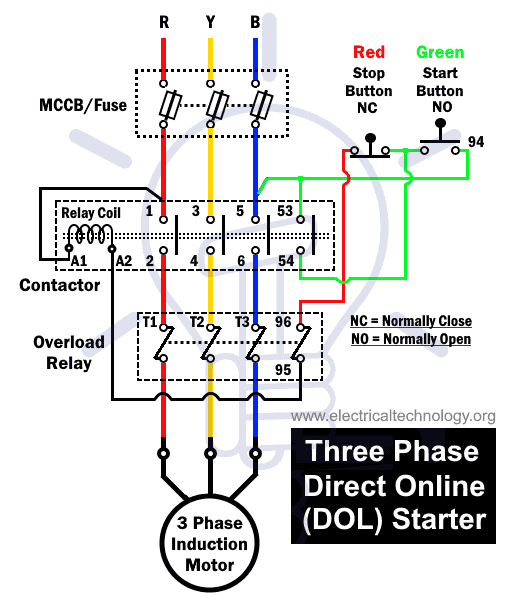
Image: styleced.blogspot.com
Deciphering the Code: Interpreting Wiring Diagrams
With the fundamental components understood, let’s delve into the art of interpreting these diagrams. Imagine each wire as a thread connecting different parts of the puzzle. These threads form specific paths, and understanding these paths is key to deciphering the diagram.
1. Tracing the Current Path: Begin by identifying the power supply lines and follow the flow of current. In a typical starter, current travels from the power lines through the contactor when it’s closed and then to the motor. In the event of an overload, the overloads will interrupt this flow.
2. Analyzing Control Circuits: Examine the control circuits, which determine how the contactor is energized or de-energized. This involves tracing the paths created by control wires, which are often connected to push buttons, relays, or timers.
3. Identifying Safety Features: Pay close attention to the wiring of safety devices, particularly the overload relays. Ensure that they are properly connected and that their operation is integrated with the motor control circuit.
Practical Tips for Wiring and Troubleshooting
Armed with knowledge, let’s move to practical application. Wiring and troubleshooting 3-phase motor starters require a combination of technical skills and safety awareness. Here are a few tips to guide you through the process.
- Safety First: Always work with electricity with the utmost care. Disconnect power before working on live components.
- Understanding the Diagram: Thoroughly analyze the diagram before attempting any wiring or troubleshooting. Identify the specific motor, starter, and control components used.
- Testing and Verification: After completing wiring, always test the starter thoroughly and confirm correct operation. Use a multimeter to verify voltage and current levels at different points in the circuit.
- Documentation: Maintain detailed records of wiring, including any modifications. This will assist in troubleshooting later.
- Professional Assistance: If you are unsure of any aspect of the wiring or troubleshooting process, don’t hesitate to consult a qualified electrician.
Remember, understanding 3-phase motor starter wiring diagrams is an essential skill for anyone working with electrical equipment. It unlocks the secrets of motor control, ensuring safe and reliable operation of industrial machines. Always prioritize safety and seek professional help when necessary.
FAQ
Q: What are the main types of 3-phase motor starters?
A: Common types include:
- Across-the-line starters
- Reduced voltage starters (autotransformer, star-delta)
- Soft starters
- Variable frequency drives (VFDs)
<br>
<strong>Q: How can I find the correct wiring diagram for my motor starter?</strong>
A: The diagram is usually included in the motor starter’s user manual or technical documentation. You can also find diagrams online by searching for the specific make and model of your starter.
Q: Is there any software that can help me create or interpret wiring diagrams?
A: Yes, specialized software like AutoCAD Electrical, EPLAN, or See Electrical can assist in creating and interpreting wiring diagrams.
Q: Where can I find online resources for learning more about 3-phase motor starters?
A: Online resources like the National Electrical Code (NEC) website, electrical engineering forums, and YouTube tutorials can provide valuable information on motor starters and wiring diagrams.
3 Phase Motor Starter Wiring Diagram Pdf
Conclusion
By mastering the art of understanding 3-phase motor starter wiring diagrams, you gain a deeper understanding of how electrical systems power industrial machines. From troubleshooting to wiring and maintenance, these diagrams are your guide to navigating the complex world of motor control. Remember, safety always comes first, so prioritize it in every step of your journey.
Are you keen to explore the fascinating intricacies of 3-phase motor starter wiring diagrams? Share your thoughts below, and let’s continue the conversation.


