
Ever faced a puzzling jumble of wires beneath a Copeland single-phase compressor? You’re not alone. These seemingly complex diagrams often bewilder even seasoned refrigeration technicians. But fear not! This guide will break down the complexities of Copeland single-phase compressor wiring, empowering you to confidently navigate the intricacies of refrigeration system setup and troubleshooting.

Image: www.pinterest.ca
Understanding the wiring diagram for a Copeland single-phase compressor is essential for anyone working with refrigeration systems. These diagrams serve as the blueprint for connecting the components, ensuring proper operation and preventing electrical hazards. This article delves into the fundamentals of these diagrams, exploring the key components, common connections, and practical tips for deciphering them with ease.
Key Components and Their Roles
Before diving into the wiring itself, let’s familiarize ourselves with the essential components that make up a single-phase compressor system:
1. The Compressor
The heart of the system, the compressor, is responsible for compressing the refrigerant, raising its pressure and temperature. It’s powered by an electric motor that converts electrical energy into mechanical energy, driving the compressor’s internal mechanism.
2. The Motor Starter
This device controls the starting and stopping of the compressor motor. Typically, a contactor or relay is used to initiate the motor’s operation. An overload relay acts as a safety mechanism, tripping the circuit if there’s excessive current, preventing damage to the motor.
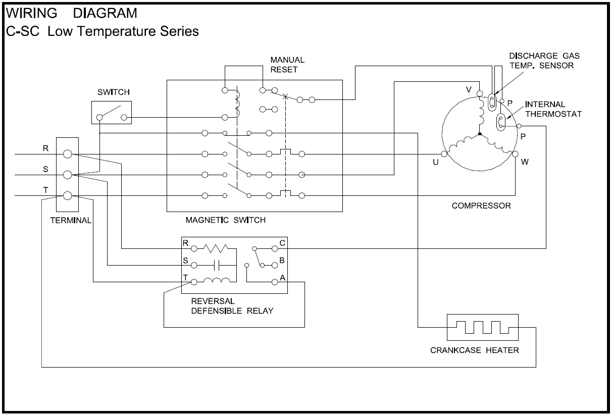
Image: 2020cadillac.com
3. The Control Circuit
This circuit monitors the system’s operation and regulates the compressor’s start-up and shut-down. The control circuit uses sensors such as pressure switches and temperature sensors to determine the optimal operating conditions of the system.
4. The Condenser
The condenser is responsible for removing heat from the refrigerant, releasing it into the surrounding environment. In air-cooled systems, fans circulate air, while water-cooled systems utilize water flow for heat dissipation.
5. The Evaporator
The evaporator is where the refrigerant absorbs heat from the environment, chilling the air or liquid. This cooling process is essential for both domestic and commercial refrigeration applications.
Deciphering the Wiring Diagram
Now that we’ve outlined the key players, let’s explore the wiring diagram itself. The arrangement of wires on the diagram can appear daunting but becomes clear with systematic analysis. Here’s a breakdown of common wiring connections:
1. Power Supply Connections
The diagram highlights the primary power source, typically a single-phase AC power supply (usually 115V or 230V). Observe the terminals labeled “L” (Live) and “N” (Neutral) – connecting to the power supply cables brings life to the system.
2. Motor Winding Connections
The compressor motor has multiple windings, usually two or three-phase, which are connected to the motor starter circuit. The wiring diagram indicates these connections using labels like “T1,” “T2,” and “T3,” which correspond to the motor’s stator windings. These connections should be made with extreme care to ensure the correct phase sequence for proper motor operation.
3. Control Circuit Connections
The control circuit interacts with pressure and temperature sensors, relays, and the motor starter. The wiring diagram depicts these connections using distinct symbols and labels. These connections control the compressor’s start and stop cycles, ensuring consistent temperature regulation within the refrigeration system.
4. Compressor Protection Connections
Safety is paramount in refrigeration systems. The wiring diagram will likely show connections to essential safety components, including overload relays and thermal switches. These components prevent damage to the motor and protect against overheating. Ensure these connections are accurate and properly grounded to prevent electrical hazards.
Troubleshooting with the Wiring Diagram
The wiring diagram isn’t just for installation but also proves invaluable during troubleshooting. By carefully examining the diagram, you can trace connections, identify potential problems, and diagnose issues.
1. Identify Potential Short Circuits
If the system exhibits unusual noises or malfunctions, inspect the wiring diagram for possible short circuits. Look for wires that might be touching or have compromised insulation. Using a multimeter to test for continuity can pinpoint a short circuit and help with its repair.
2. Verify Control Circuit Operation
If the compressor isn’t starting, check the control circuit indicated on the diagram. Test if components like pressure switches, temperature sensors, and relays are functioning correctly. A multimeter can verify continuity and voltage levels within the control circuit, revealing potential failures.
3. Inspect Grounding
Grounding is crucial for electrical safety. Ensure proper connection of the ground wires, which are generally colored green or yellow-green, to the designated grounding component on the system’s frame or chassis. Review the wiring diagram for accurate grounding connections to prevent electrical shocks and ensure user safety.
Staying Up-to-Date
The world of refrigeration technology is constantly evolving. New compressor models are introduced frequently, each with its unique wiring configurations and features. Staying abreast of the latest advancements is essential. Consulting the manufacturer’s instructions, online resources, and attending technical training sessions will equip you with the knowledge to handle modern Copeland compressors with confidence.
Copeland Single Phase Compressor Wiring Diagram
Conclusion
Mastering the Copeland single-phase compressor wiring diagram isn’t just about reading lines and symbols; it’s about understanding the logic behind the connections, the role of each component, and the interconnectedness of the entire system. By deciphering this diagram with care, you gain the skills to install, troubleshoot, and maintain refrigeration systems efficiently, ensuring reliable operation and minimizing potential hazards.
Remember, always prioritize safety, consult the manufacturer’s specifications, and don’t hesitate to seek professional guidance when faced with unfamiliar or complex situations. The knowledge gleaned from this guide empowers you to confidently tackle the challenges of refrigeration system wiring and ensures the smooth operation of your cooling solutions.


